Contact Kelly McNamara for information on products, services or locations.
Choosing the right Changeover Switch in 2026 requires more than comparing prices or catalog photographs. Global buyers face different grid systems, installation rules, climate conditions, and maintenance expectations. A compact manual switch may suit a small commercial panel. A motorized automatic transfer switch may be safer for hospitals, data centers, and manufacturing lines.
Electrical safety specialist Jim Dollard has emphasized, “Reliable power transfer begins with reliable design.” This principle remains practical. Buyers should verify rated operational voltage, current capacity, pole configuration, short-circuit withstand, and switching method. Open-transition models briefly interrupt power. Closed-transition models reduce interruption but require stricter coordination and approval. These details affect equipment safety, uptime, and total ownership cost.
Look beyond the label.
A dependable selection should match IEC 60947-6-1, IEC 60947-3, UL 1008, or the applicable regional standard. Certification alone is not enough. Factory testing, enclosure protection, terminal quality, service access, and spare-part availability also matter. Outdoor projects may need stronger corrosion resistance and higher IP protection. Remote sites may need simpler mechanisms, because advanced controls can be difficult to repair.
Some decisions remain imperfect. A premium model does not always deliver better value. A lower-cost unit may perform well in a controlled environment, yet fail under frequent transfers or poor maintenance. Buyers should request test reports, wiring diagrams, installation limits, and real application references. This guide compares the main Changeover Switch types for global purchasing decisions, while recognizing that local engineers must confirm the final specification.
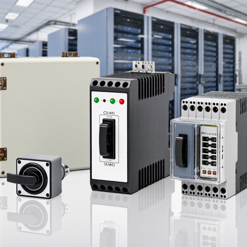
A changeover switch connects a load to one of two power sources, such as the utility supply and a generator. When the primary source fails, the switch transfers the load to the alternative source. Manual models require an operator; automatic transfer switches detect supply conditions and act without waiting for someone to reach the panel. That difference matters during an overnight outage. The U.S. Energy Information Administration reported an average of about 5.5 hours of power interruptions per customer in 2023, including major events. This national figure is useful context, not a prediction for any particular site.
Inside an automatic unit, monitoring circuits check voltage and frequency. If readings move outside set limits, the mechanism opens one source before closing the other in a typical open-transition design. This break-before-make action helps prevent unintended source connection. Some systems use closed transition, but only where the equipment and installation are designed for it. Selection is not just about matching current ratings. Buyers should also check pole count, short-circuit withstand capability, enclosure rating, operating temperature, and generator start delay. IEC 60947-6-1 provides requirements for transfer switching equipment. Still, a standard cannot replace a site-specific review. Neutral switching and grounding arrangements deserve particular care; overlooking them is an easy mistake.

In 2026, global buyers will encounter several changeover switch types, each suited to different loads and operating conditions. Manual switches use a handle and suit sites where trained staff can transfer power safely. Automatic transfer switches detect supply failure and move loads to a standby source without waiting for an operator. That matters in hospitals, data rooms, and production lines. Static transfer switches use semiconductor devices for very rapid transfers, often protecting sensitive electronic equipment. Speed is not the only factor.
Transfer mode also matters. Open-transition switches disconnect one source before connecting another, avoiding overlap. Closed-transition designs briefly connect both sources, but require careful system coordination. Bypass-isolation models let technicians service switching equipment while maintaining power to the load. The IEC 60947-6-1 standard covers transfer switching equipment, a useful reference when comparing specifications. The International Energy Agency’s Electricity 2024 report says global electricity demand grew 2.2% in 2023 and forecasts average annual growth of 3.4% for 2024–2026. That demand outlook makes continuity planning more relevant, though it does not dictate one switch type. Check load criticality, transfer time, fault rating, and maintenance access. A datasheet alone can miss awkward site realities.
Global buyers should match the changeover switch type to the load, transfer speed, and local grid conditions. Open-transition automatic transfer switches suit generators and emergency lighting. Delayed-transition units protect motors by allowing residual voltage to decay. Closed-transition designs reduce interruption time, but they require careful synchronization and utility approval.
The International Energy Agency’s Electricity 2024 report projects data-center electricity use will exceed 1,000 TWh in 2026, compared with about 460 TWh in 2022. This growth increases demand for dependable automatic transfer equipment.
Check rated current, frequency, poles, short-circuit withstand, and transfer time. For three-phase systems, confirm whether the neutral must switch. A four-pole device may prevent unwanted neutral currents in separately derived supplies.
Standards matter more than appearance. IEC 60947-6-1 covers transfer switching equipment, while UL 1008 is widely specified in North American projects. NFPA 110 addresses emergency and standby power performance.
Buyers should also verify IP protection, altitude derating, ambient temperature, endurance category, and control-voltage tolerance. A switch rated for 400 A at sea level may need derating at a hot, high-altitude site.
No specification is perfect. Field audits still find mismatched breaker ratings, unclear neutral arrangements, and untested generator interfaces. Request routine-test records, type-test evidence, wiring diagrams, and local certification before approval.
Selecting a changeover switch starts with the system, not the product catalogue. Identify the normal and backup power sources first. Then check voltage, continuous current, short-circuit withstand, and switching frequency. A small office may only need a manual switch. A hospital pump or data room usually needs automatic transfer and a controlled transition.
Count the poles carefully. A three-phase system may require neutral switching, especially when sources have different grounding arrangements. Confirm this with a qualified electrical professional. For motors, pumps, and compressors, consider inrush current rather than relying on the nameplate current alone. Transfer time also matters. Sensitive equipment may restart during a brief interruption.
Look at the installation environment. Dust, moisture, heat, and limited panel space can affect service life. Choose an enclosure and terminal layout that technicians can inspect without removing nearby wiring. Interlocking is essential. It helps prevent both sources from connecting together. Test the switch under realistic load conditions, not only with a light test lamp.
Manual operation is simple, but it depends on trained personnel. Automatic systems improve response, yet their controls require regular testing. This is where selection often becomes less certain. A switch may meet the electrical rating but still fail the site’s maintenance routine. Leave space for inspection. Small details matter.
Choosing a changeover switch begins with the load, supply arrangement, and switching purpose. Manual switches suit simple backup systems and direct operator control. Automatic models transfer power when the primary supply fails. A bypass type can support maintenance without interrupting essential circuits. Select the correct current, voltage, pole configuration, short-circuit rating, and enclosure protection. An oversized enclosure is not automatically safer.
Installation should leave clear space around terminals and moving parts. Qualified electricians must verify isolation before wiring. Cable lugs need firm torque, not excessive force. Incorrect tightening can create heat later. Label normal and emergency positions clearly. Safety interlocks should prevent unsafe parallel connection between sources. Local electrical requirements still control the final design.
Tips: Inspect terminals after the first operating cycle. Dust, vibration, and moisture may reveal weaknesses that commissioning misses. During maintenance, check contact discoloration, mechanical stiffness, insulation condition, and enclosure seals. Keep a dated service record with test results and replaced parts. Supplier evaluation should include type-test evidence, wiring diagrams, spare-part availability, production traceability, and realistic delivery information. Ask how the switch performs under repeated transfers, not only its maximum rating. A low price may hide limited testing or weak technical support. I have seen tidy documents fail to answer basic fault questions. That is a warning worth recording.
| Switch type | Transfer method and typical use | Installation considerations | Safety considerations | Maintenance focus | Supplier evaluation criteria |
|---|---|---|---|---|---|
| Manual changeover switch | An operator moves the load between utility and an alternate source. Common for standby generators and installations where a brief interruption during transfer is acceptable. | Confirm the switch rating, number of poles, enclosure, cable terminations, and suitability for the system’s earthing and neutral arrangement. Installation should follow local electrical rules and the manufacturer’s instructions. | Use an approved interlocking arrangement to prevent unintended connection of incompatible sources. Provide clear source identification and safe operating access; never rely on operating procedure alone where mechanical interlocking is required. | Inspect the enclosure, terminals, operating mechanism, and interlock. Check for damage, contamination, or signs of overheating, following the manufacturer’s maintenance instructions. | Request documented ratings, applicable test reports, installation instructions, spare-parts availability, warranty terms, and evidence that the product is certified or approved for the destination market. |
| Automatic open-transition transfer switch | Automatically disconnects one source before connecting the other (“break before make”). Used where automatic backup transfer is needed and a short interruption is acceptable. | Check source voltage and frequency limits, control-power needs, sensing settings, system grounding, neutral switching requirements, and coordination with upstream protection. Commissioning should verify operation on both sources. | Ensure the equipment prevents unintended parallel connection of sources. Confirm that the available fault current does not exceed the switch’s documented short-circuit withstand or closing rating for the specified protective-device combination. | Test sensing, control functions, alarms, and transfer operation as directed by the manufacturer. Inspect power connections and verify that protective devices and control settings remain appropriate after system changes. | Evaluate supported electrical configurations, published transfer logic, control documentation, service support, commissioning assistance, and compatibility with the project’s generator or alternate source. |
| Automatic closed-transition transfer switch | Briefly overlaps the sources during transfer (“make before break”) to reduce interruption. Appropriate only where the system and utility or source authority permit momentary paralleling. | Requires compatible sources and controls designed for synchronization and permitted overlap. Confirm utility approval, protection and interconnection requirements, operating modes, and commissioning responsibilities before selection. | Source paralleling can create significant electrical and operational risks if not properly engineered. Verify synchronism-check and protective functions, approved operating limits, and compliance with applicable local interconnection rules. | Have qualified personnel verify synchronization controls, protective functions, settings, and transfer sequences at the intervals specified by the manufacturer and applicable rules. | Require clear documentation of permitted paralleling duration and conditions, protection and control functions, applicable approvals, factory test evidence, and access to qualified commissioning and service personnel. |
| Bypass-isolation transfer switch | Combines transfer capability with a means to bypass and isolate the transfer-switch mechanism, allowing certain maintenance tasks while the load remains supplied through the bypass path. | Plan the bypass sequence, isolation clearances, equipment footprint, cable routing, and access for operation and maintenance. Confirm that the selected configuration suits the required source arrangement and load continuity needs. | Verify that bypass and isolation positions are clearly indicated and mechanically interlocked as designed. Follow the documented operating sequence; bypass equipment does not remove the need for safe isolation procedures. | Inspect and exercise the transfer and bypass mechanisms in accordance with the manufacturer’s instructions. Confirm position indication, interlocks, terminals, and the condition of accessible components. | Compare the documented bypass procedure, maintenance access, interlock design, replacement-part support, service training, and any required listing or certification for the intended installation. |
Selection note: Ratings, pole configuration, neutral treatment, fault-current capability, certification, and maintenance requirements depend on the system design and destination market. Standards such as IEC 60947-6-1 or UL 1008 may be relevant in applicable markets; confirm the required standard and approval with the project engineer and local authority.